Integration guide
Before you build
About this guide
This is a technical guide for connecting physical battery systems to the Tensor Cloud battery optimization service. It is aimed at:
- System integrators implementing battery optimization solutions
- EMS developers building gateway connections to Tensor Cloud
- Technical stakeholders responsible for energy storage system operations
This guide consists of two parts: The guide itself, and communication protocol specifications in AsyncAPI format. The guide provides an overview of the integration process, technical requirements, and operational responsibilities. The AsyncAPI specification contains detailed message schemas, telemetry requirements, and command structures.
We highly recommend making yourself familiar with the AsyncAPI specification before starting the integration process, as it contains all necessary details on the communication protocol, and guidance on automatic client code generation.
Before building an integration with Tensor Cloud, make sure you contact our technical team for detailed guidance and for getting access to a Tensor Cloud development workspace.
Terminology
| Term | Meaning |
|---|---|
| EMS | Energy Management System: the on-site controller that reads telemetry and executes battery commands. |
| TSO | Transmission System Operator: the regional grid operator (e.g. TEPCO PG, Chubu). |
| OCCTO | Organization for Cross-regional Coordination of Transmission Operators: Japan's nationwide grid coordinator. |
| JEPX | Japan Electric Power Exchange: the wholesale electricity spot market. |
| FIT / FIP | Feed-in Tariff / Feed-in Premium: Japan's renewable-energy support schemes. |
| FCR | Frequency Containment Reserve (一次調整力): a primary frequency-regulation ancillary service. |
| SoC / SoE | State of Charge (%) / State of Energy (kWh) of the battery. |
| SoH | State of Health: remaining battery capacity relative to when new. |
| VPP | Virtual Power Plant: several resources aggregated into a single market resource. |
| BMS | Battery Management System: the battery's own control and monitoring unit. |
| Assessment II | The TSO's after-the-fact evaluation of delivered FCR response, computed from 1-second data. |
How Tensor Cloud works
The battery optimization API enables automated management of battery energy storage systems through real-time communication between Tensor Cloud's optimization engine and on-site Energy Management Systems (EMS). It aims to maximize the value of battery storage systems by creating economically optimal charge/discharge schedules.
It does this by aggregating technical signals from the battery system and other on-site hardware, and combining them with economic signals from electricity markets and other sources to arrive at an economically optimized battery operating schedule.
For the physical control of the battery system, and for collecting site telemetry, Tensor Cloud relies on EMS operated and provisioned by specialized providers. While Tensor Energy has a number of established partners that can handle physical integration at any scale, we support any EMS vendor that can implement this MQTT protocol.
System overview
Note that Tensor Cloud currently only supports a single battery, solar system, and electrical load per site.
Battery system topologies
Tensor Cloud supports three main battery system topologies for battery optimization: AC-link, DC-link, and stand-alone.
Each topology has different requirements when it comes to required telemetry data that the EMS needs to send. Refer to the telemetry section for details.
AC-linked battery systems
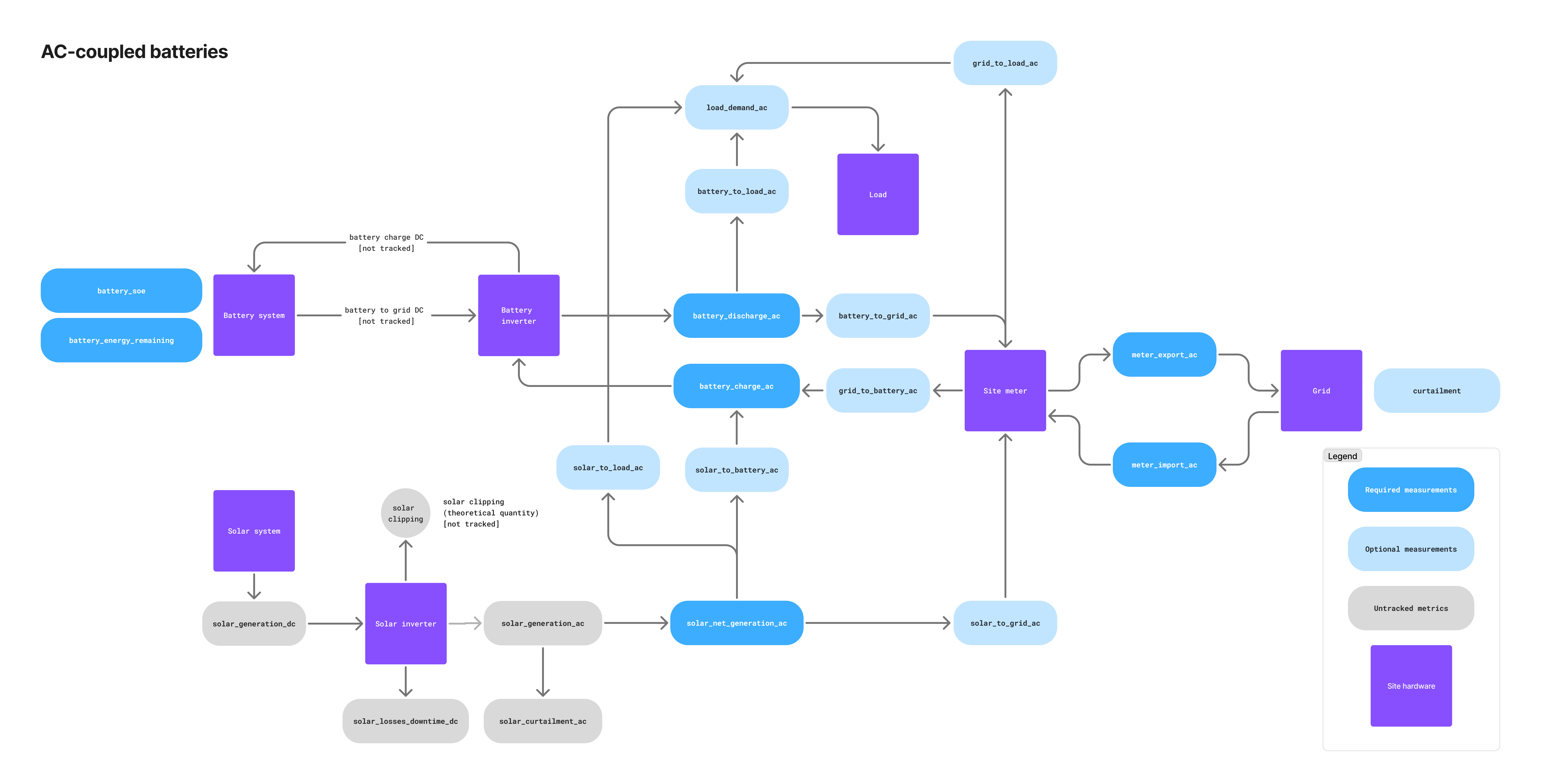
This is often the case for retrofit FIP-conversion projects where the original solar topology cannot be fundamentally changed without losing FIT/FIP certification. The battery and solar system exchange energy through their respective inverters, with an optional on-site electrical load also connected via AC.
DC-linked battery systems
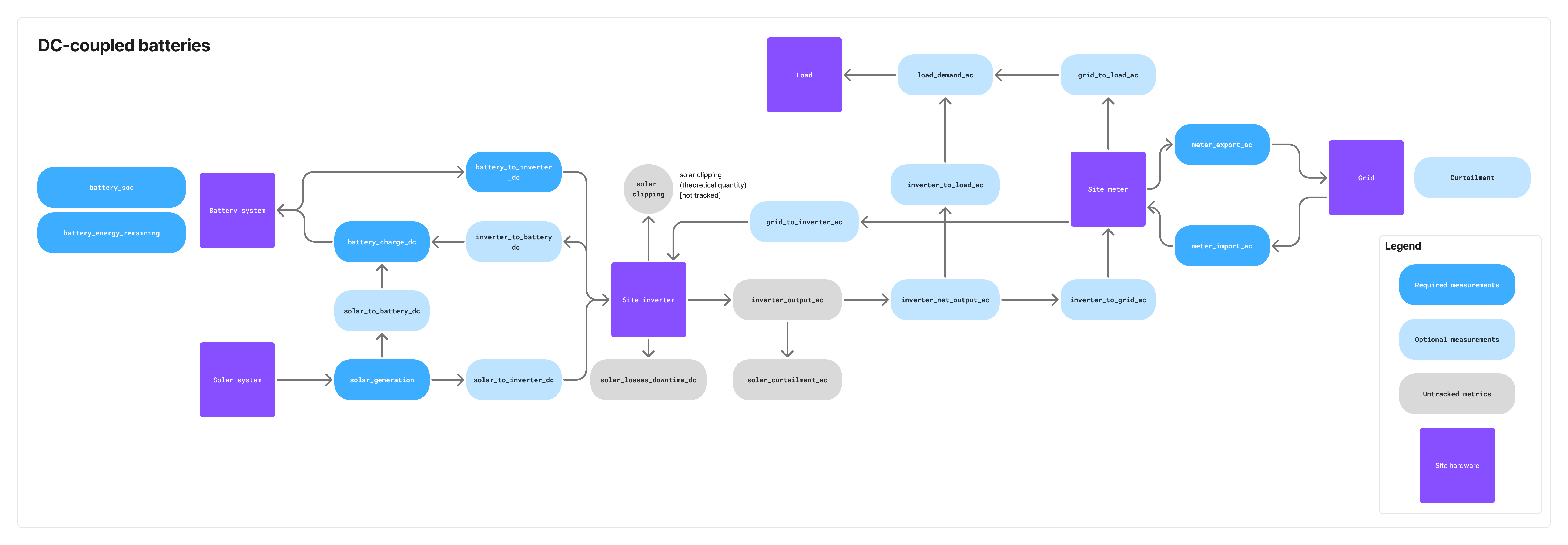
In DC-linked systems, the battery and solar PV are connected on the DC side, allowing for more efficient energy transfer. An optional on-site electrical load is also supported. This use-case is common in new installations where the system can be designed from the ground up to optimize for battery integration.
Stand-alone battery systems
Stand-alone battery systems are not co-located with solar or electrical loads. They often operate as merchant systems for exclusive participation in energy markets.
Roles and responsibilities
Tensor Cloud works under a shared responsibility model with its partners and battery system owners. Each party has specific roles and responsibilities in the integration and operation of the battery optimization service.
| Party | Responsibilities |
|---|---|
| Tensor Energy | • Economic optimization and schedule generation • Soft guarantees of battery system owner preferences (e.g., min/max SoE) |
| Integrator/EMS | • EMS uptime management and guarantees in alignment with battery owner • Accurate telemetry reading from site hardware according to the protocol specifications • Local enforcement of TSO constraints (e.g., battery ramp rates, curtailment, data logging requirements) • Hard guarantees of battery system owner preferences (e.g., min/max SoE) • Emergency response and EMS hardware fault handling |
| Battery system owner | • Imbalance responsibility (depending on contract terms, this could be shared with Tensor Energy) • Relationship management with TSO and other stakeholders like OCCTO (depending on contract terms, this could be shared with Tensor Energy) |
| Battery OEM | • Hardware maintenance and support (depending on contract terms with battery system owner) • Battery firmware updates and bug fixes |
Connect to Tensor Cloud
Communication
The communication protocol used by Tensor Cloud for battery optimization is MQTT (Message Queuing Telemetry Transport) 3.1.1 over TLS 1.2+. This protocol is designed for lightweight, reliable pub/sub information exchange between the EMS and Tensor Cloud.
Endpoints
The Tensor Cloud battery optimization service is accessible via the following MQTT broker endpoints:
Testing environment: mqtt.staging.tensorenergy.jp:8883
Production environment: mqtt.tensorenergy.jp:8883
The testing environment is used during the integration development phase and for post-integration testing. The production environment is used for live operations once the integration is complete and validated.
Authentication
Tensor Cloud uses X.509 certificates for secure authentication with our MQTT broker. Each EMS gateway or software application must have its own unique certificate. Your technical contact at Tensor Energy will provide certificates for development and production environments on request within 24 hours.
Certificates are scoped to specific topics on the MQTT broker, which means that each certificate can only publish and subscribe to the topics it is authorized for. This ensures that your EMS can only interact with the data and commands relevant to the site it is installed at.
Certificates issued by Tensor do not expire and do not require periodic rotation by default. Integrators or their customers who require regular rotation can request it from the Tensor technical team.
Each certificate may be used by only one concurrent MQTT connection. This is enforced by AWS IoT Core: when a second connection is opened with the same certificate, the older session is disconnected.
Quality of service (QoS)
Tensor Cloud supports MQTT QoS levels 0 and 1 for message delivery. Under QoS 0 messages are delivered at most once; under QoS 1 at least once. With QoS 1 the broker handles message delivery acknowledgement at the MQTT transport layer; no additional broker-level ack messages are required from your client.
This is separate from the application-level acknowledgements your EMS sends on its res_topic (typically ack-cmd/{siteId}) for every command it receives (see Command lifecycle). Those are required regardless of QoS because they carry validation results, not delivery confirmation.
MQTT topics
All communication between the EMS and Tensor Cloud is done through MQTT topics in a publish/subscribe fashion. The topic structure is designed to be intuitive and follows a hierarchical format based on site and device identifiers.
Site and gateway IDs
Understanding the relationship
- Site ID (
siteId): Represents a single physical installation location (e.g., one battery storage facility). This identifier is used for command topics since commands are sent to the site level. - Gateway ID (
gatewayId): Represents a specific EMS device or software instance that collects telemetry and executes commands for a site. This identifier is used in telemetry topics to distinguish which gateway device is reporting.
Common configurations
-
Single gateway per site (typical): One physical EMS device installed at the site
- Example: Site
si_qcf9gnhas gatewaygw_0uv3tf - All telemetry from this site uses
dt/si_qcf9gn/gw_0uv3tf/... - Commands are sent to
cmd/si_qcf9gn/...
- Example: Site
-
Hot standby: Both primary and standby devices are connected to the MQTT broker
- Example: Site
si_qcf9gnhas gatewaysgw_0uv3tf(primary) andgw_dwj4n2(standby) - Both devices subscribe to
cmd/si_qcf9gn/... - Only the active gateway publishes telemetry, acknowledges commands, and executes schedules. The standby gateway receives commands but does not ack or execute until it is promoted to active. This avoids duplicate
ack-cmdmessages and double-execution of schedules. Primary/standby coordination is the EMS partner's responsibility. - On failure, standby takes over and starts publishing telemetry, acks, and executing schedules using
dt/si_qcf9gn/gw_dwj4n2/.../ack-cmd/si_qcf9gn. - Each gateway has its own unique certificate
- Example: Site
-
Cold standby: Only the primary device is connected to the MQTT broker
- Example: Site
si_qcf9gnhas gatewaysgw_0uv3tf(primary) andgw_dwj4n2(standby) - Primary publishes telemetry using
dt/si_qcf9gn/gw_0uv3tf/... - Standby device is physically on site but NOT connected to the broker
- On primary failure, standby connects and publishes using
dt/si_qcf9gn/gw_dwj4n2/... - Each gateway has its own unique certificate
- Example: Site
Important notes
- Each certificate can publish/subscribe to topics for only the sites it is authorized for
- For redundancy setups, each physical gateway device must have its own certificate
- One certificate can only be used for one concurrent connection to the broker
Topic overview
The diagram below shows the core telemetry and command flows. The alert (.../alert, .../alert/active), irradiation, and 1 Hz frequency topics are described in their respective sections.
Message format
All messages published to the MQTT broker use JSON format. The payload structure is defined in the protocol schema, which includes telemetry messages and command formats expressed in JSON schema. The schema provides detailed definitions for each message type, including required fields, data types, and validation rules.
Message envelope essentials
message_id: every message carries a uniquemessage_idof the formmsg_<uuid>, amsg_prefix followed by a lowercase UUIDv4, matching^msg_[0-9a-f]{8}-[0-9a-f]{4}-[0-9a-f]{4}-[0-9a-f]{4}-[0-9a-f]{12}$. When resending a sample, reuse its originalmessage_idso Tensor Cloud can deduplicate.schema_version: every message includes the protocol version it was produced under (currently2.6.0).- Timezone: every
*_tsfield is an ISO-8601 timestamp with an explicit offset. Tensor Cloud operates in Japan Standard Time (+09:00); use it for all timestamps and avoid a bareZ. {window}token: in windowed energy topics (.../energy/{window}),{window}is an ISO-8601 duration and must be one ofPT1M,PT5M,PT10M,PT15M,PT30M,PT1H.- Forward compatibility: messages may carry fields introduced by newer schema revisions (
additionalProperties: true). Parse the fields you know and ignore unknown ones rather than rejecting the message.
Timestamp boundary convention
All time windows in the protocol use left-inclusive, right-exclusive boundaries: [start_ts, end_ts)
This convention applies to:
- Windowed energy telemetry (
measurement_value.start_tsandmeasurement_value.end_ts) - Curtailment schedules (
start_tsandend_ts) - Battery power command schedules (
control.schedule[].start_tsandcontrol.schedule[].end_ts) - FCR offer command schedules (
control.schedule[].start_tsandcontrol.schedule[].end_ts)
Example: A time window with end_ts of 2024-01-04T10:30:00.000+09:00 includes all times up to but not including 10:30:00. This means it includes 10:29:59.999... but not 10:30:00.000.
This convention ensures adjacent time windows connect seamlessly without gaps or overlaps:
- Window 1:
[10:00:00, 10:30:00)→ includes 10:00:00, excludes 10:30:00 - Window 2:
[10:30:00, 11:00:00)→ includes 10:30:00, excludes 11:00:00
Publish telemetry to Tensor Cloud
What to publish
Site hardware telemetry (e.g., site meter discharge, solar generation, battery SoE) is published by the EMS using a unified dt/ topic prefix, followed by the site ID, gateway ID, and an ending specific to the type of telemetry (lifetime, windowed, instantaneous, state), resulting in the following formats:
Lifetime metric topic structure:
dt/{siteId}/{gatewayId}/{metric}/lifetime

Windowed metric topic structure:
dt/{siteId}/{gatewayId}/{metric}/energy/{window}

Instantaneous metric topic structure:
dt/{siteId}/{gatewayId}/{metric}/power

State metric topic structure:
dt/{siteId}/{gatewayId}/{metric}/state
Some telemetry uses a fixed topic tail instead of the {metric}/{type} patterns above: dt/{siteId}/{gatewayId}/curtailment, dt/{siteId}/{gatewayId}/irradiation, dt/{siteId}/{gatewayId}/solar, dt/{siteId}/{gatewayId}/frequency, dt/{siteId}/{gatewayId}/alert, and dt/{siteId}/{gatewayId}/alert/active.
The site ID and gateway ID are unique identifiers assigned to each site and its associated EMS gateway. They will be provided to you by your technical contact at Tensor Energy together with each set of certificates.
For a list of telemetry types and their definitions, see the tables below and the protocol schema.
Telemetry data types
Tensor Cloud supports four types of telemetry data for each metric. The following table shows the relationship between data types, MQTT topic patterns, formats, and requirements:
| Type | MQTT Topic Pattern | Unit | Value Semantics | Required? |
|---|---|---|---|---|
| Instantaneous power | dt/{siteId}/{gatewayId}/{metric}/power | kW | Instantaneous power value at measurement time. All values ≥ 0 (direction encoded in metric name). | ⚪️ Optional - can enhance accuracy when sent at high frequency (≤10 min), but cannot replace energy readings. |
| Windowed energy | dt/{siteId}/{gatewayId}/{metric}/energy/{window} | kWh | Energy consumed/generated during a specific time window (e.g., PT30M = 30 minutes). All values ≥ 0. | 🟡 Required (either this OR lifetime) - at least one energy reading type must be sent for optimization to work. |
| Lifetime energy | dt/{siteId}/{gatewayId}/{metric}/lifetime | kWh | Cumulative energy since commissioning (increasing counter, similar to electricity meter). Tensor Cloud handles counter resets. All values ≥ 0. | 🟡 Required (either this OR windowed) - at least one energy reading type must be sent for optimization to work. |
| State | dt/{siteId}/{gatewayId}/{metric}/state | kWh | Instantaneous state value at measurement time (e.g., battery State of Energy, battery_soe). All values ≥ 0. | 🔴 Required - battery State of Energy (battery_soe) must be sent for optimization to work. |
EMS must send at least one energy reading type (windowed OR lifetime) for Tensor Cloud battery optimization to function correctly. Instantaneous power readings are optional and can improve accuracy when sent frequently, but cannot replace energy readings.
Missing data
This guidance applies to numeric telemetry (power, windowed energy, lifetime energy, battery state, irradiation), where measurement_value.value is a single number.
If the EMS cannot read a numeric value from the underlying resource (battery, inverter, meter, etc.) at a given timestamp, skip the publish for that metric at that timestamp. Resume publishing when data becomes available again.
value: nullis not valid:measurement_value.valueis typed asnumber, sonullfails schema validation.value: 0is also discouraged: it is indistinguishable from a genuine zero reading and would be treated as real data by the optimization engine.- If the underlying resource fails for an extended period, publish an
AlertEventondt/{siteId}/{gatewayId}/alertwith the appropriateAlertCodeso Tensor Cloud is notified of the upstream issue.
Structured telemetry such as curtailment (whose measurement_value is a schedule array, not a scalar) has its own semantics: publish what you can observe, and document any source-data limitations to the Tensor team. For solar DC telemetry (dt/{siteId}/{gatewayId}/solar), voltage and current are a matched pair: if either cannot be read at a given timestamp, skip the publish for that timestamp rather than sending one value alone.
Common to all topologies
Legend: 🔴 Required · ⚪️ Optional · 🟡 Conditional (required under the condition stated in the metric's description).
| Telemetry name | Required/Optional | Description |
|---|---|---|
meter_export_ac | 🔴 Required | Amount of energy exported to the grid measured at the main site meter. |
meter_import_ac | 🔴 Required | Amount of energy imported from the grid measured at the main site meter. |
battery_soe | 🔴 Required | State of Energy (SoE) in kWh of the battery system. This is the amount of energy currently stored in the battery at this moment (kWh equivalent of State of Charge). Valid range: 0 ≤ battery_soe ≤ battery_energy_remaining. |
battery_energy_remaining | 🔴 Required | Total usable energy capacity of the battery system in kWh at nominal temperature (usually ~25°C) accounting for cell degradation and faulty cells. This represents the maximum energy the battery can hold and should be updated when capacity changes due to degradation or temperature effects. Unlike battery_soe which changes frequently, this value typically updates once per day or when significant capacity changes occur. |
grid_to_load_ac | 🟡 Conditional | Amount of energy sent from the site meter to an on-site electrical load (e.g., factory). Required if on-site load exists. |
load_demand_ac | 🟡 Conditional | Total amount of energy consumed by an on-site electrical load (e.g., factory). Sum of grid_to_load_ac and either battery_to_load_ac for AC-link, or inverter_to_load_ac for DC-link. Required if on-site load exists. |
curtailment | 🔴 Required | Curtailment schedule from the TSO, captured by the EMS from the on-site curtailment device. A single publish may cover any time horizon (e.g., today + tomorrow) and any number of intervals; the only effective limit is the MQTT payload size (128 KB on AWS IoT Core). If the TSO provides separate fixed (low-priority) and update (high-priority) schedules, the EMS must resolve them into a single effective schedule and publish that. Each interval carries start_ts, end_ts, and limit_percent (0–100, the permitted output as a percentage of capacity). |
Understanding battery capacity metrics
| Metric | Description | Send to Tensor Cloud |
|---|---|---|
battery_energy_remaining | Effective battery capacity in kWh accounting for degradation and faulty cells | Once per day |
battery_soe | Current energy stored in battery (kWh). Calculate as: SoC% × battery_energy_remaining | Every 1-10 minutes |
When calculating battery_soe from SoC percentage, always multiply by battery_energy_remaining (effective capacity), not nominal capacity.
Example: Battery with 3,000 kWh nominal capacity, degraded to 2,800 kWh effective capacity, at 50% SoC:
- Correct:
battery_soe = 50% × 2,800 kWh = 1,400 kWh - Wrong:
battery_soe = 50% × 3,000 kWh = 1,500 kWh(will cause incorrect optimization)
AC-linked telemetry
| Telemetry name | Required/Optional | Description |
|---|---|---|
solar_net_generation_ac | 🔴 Required | Solar generation after subtracting curtailment. Sum of solar_to_load_ac, solar_to_battery_ac, and solar_to_grid_ac. |
battery_charge_ac | 🔴 Required | Amount of energy charged into the battery system, usually measured at the battery meter or monitoring system. Sum of grid_to_battery_ac and solar_to_battery_ac. |
battery_discharge_ac | 🔴 Required | Amount of energy discharged from the battery system, usually measured at the battery meter or monitoring system. Sum of battery_to_grid_ac and battery_to_load_ac. |
solar_to_grid_ac | ⚪️ Optional | Amount of energy sent directly from the solar system to the site meter. |
solar_to_battery_ac | ⚪️ Optional | Amount of energy sent from the solar system to the battery. |
solar_to_load_ac | ⚪️ Optional | Amount of energy sent from the solar system to an on-site electrical load (e.g., factory). |
battery_to_grid_ac | ⚪️ Optional | Amount of energy sent from the battery to the grid measured at the main site meter. |
battery_to_load_ac | ⚪️ Optional | Amount of energy sent from the battery to an on-site electrical load (e.g., factory). |
grid_to_battery_ac | 🟡 Conditional | Amount of grid energy sent to the battery measured at the main site meter. Required if the battery system can charge from the grid. |
irradiation | 🔴 Required | On-site solar irradiation sensor reading in kW/m2. Used to improve solar generation forecasts and optimize battery charging. Published to dt/{siteId}/{gatewayId}/irradiation. |
DC-linked telemetry
| Telemetry name | Required/Optional | Description |
|---|---|---|
solar_generation_dc | 🔴 Required | Amount of energy generated by the solar system measured on the DC side. Sum of solar_to_battery_dc and solar_to_inverter_dc. |
battery_charge_dc | 🔴 Required | Amount of energy charged into the battery system measured on the DC side. Sum of solar_to_battery_dc and inverter_to_battery_dc. |
battery_to_inverter_dc | 🔴 Required | Amount of energy sent from the battery to the site inverter. Measured on the DC side. |
inverter_net_output_ac | 🟡 Conditional | Total AC-side output of the site inverter. Sum of inverter_to_load_ac and inverter_to_grid_ac. Measured on the AC side. Required in case of an on-site electrical load. |
solar_to_battery_dc | ⚪️ Optional | Amount of energy sent from the solar system to the battery. Measured on the DC side. |
solar_to_inverter_dc | ⚪️ Optional | Amount of energy sent from the solar system to the site inverter. Measured on the DC side. |
inverter_to_battery_dc | ⚪️ Optional | Amount of energy sent from the inverter to the battery. Measured on the DC side. |
inverter_to_load_ac | 🟡 Conditional | Amount of energy sent from the inverter to an on-site electrical load (e.g., factory). Measured on the AC side. Required if on-site load exists. |
inverter_to_grid_ac | ⚪️ Optional | Amount of energy sent from the inverter to the grid. Measured on the AC side. |
grid_to_inverter_ac | 🟡 Conditional | Amount of grid energy sent to the inverter. Measured on the AC side. Required if the battery system can charge from the grid. |
irradiation | 🔴 Required | On-site solar irradiation sensor reading in kW/m2. Used to improve solar generation forecasts and optimize battery charging. Published to dt/{siteId}/{gatewayId}/irradiation. |
solar (DC voltage and current) | 🔴 Required | PV-array DC voltage (V) and current (A), measured at the DC link upstream of the inverter as a single value aggregated across the whole array. Voltage and current are sampled at the same instant and sent together as one matched pair on dt/{siteId}/{gatewayId}/solar (SolarDcElectrical message). DC-linked systems only. |
Solar DC voltage and current. For DC-linked systems where the PV array and battery share a DC bus, publish the PV array's DC voltage and current on dt/{siteId}/{gatewayId}/solar using the SolarDcElectrical message.
- What to send: one DC voltage reading in volts (
V) and one DC current reading in amperes (A), each a single aggregate value representing the whole PV array. Both values are ≥ 0. - Where to measure: on the DC side of the system, at the PV DC link upstream of the inverter (before DC-to-AC conversion). If the array has multiple strings or MPPT inputs, report the combined array total, not per-string values.
- How to measure: sample voltage and current at the same instant and send them together in one message so the pair is time-aligned, carried under
measurement_valueasvoltageandcurrent, each a{value, unit}object. Publish instantaneous readings at 1-minute resolution; do not send averaged or scheduled values. - When it applies: required only for DC-linked PV plus battery sites. AC-linked and stand-alone sites do not send this channel.
Stand-alone telemetry
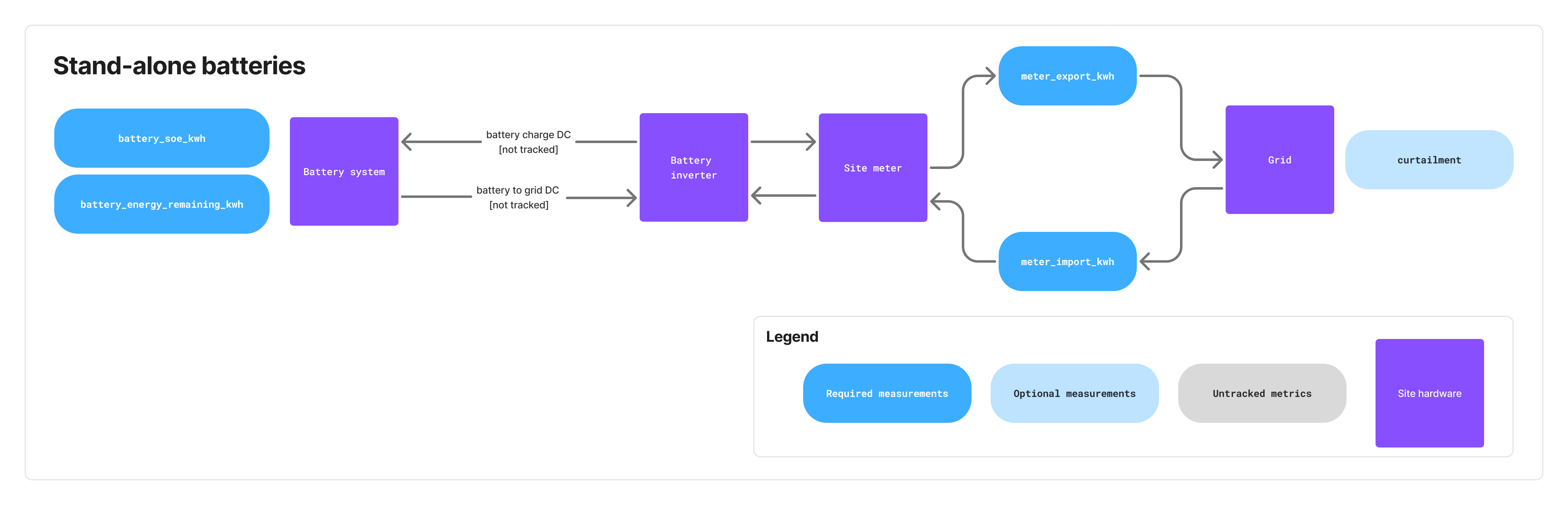 Stand-alone battery systems only require the telemetry listed in the "Common to all topologies" section above. Since there is no co-located solar generation, irradiation telemetry is not required.
Publishing requirements and timing
Telemetry publishing requirements
| Message Type | Minimum Frequency | Recommended Frequency |
|---|---|---|
| Energy telemetry (windowed/lifetime) | Every 10 minutes | Every 1 minute |
| Instantaneous power (if available) | Same as energy or faster | Every 1 minute or faster |
Battery state (battery_soe) | Every 10 minutes | Every 1 minute |
Solar DC voltage & current (*/solar, DC-linked) | Every 1 minute | Every 1 minute |
battery_energy_remaining | Once per day | Once per day |
Alert snapshot (alertState) | Every 10 minutes | Every 5 minutes |
Alert events (alertEvent) | Immediately on state change | N/A |
| Curtailment schedules | On update from TSO | N/A |
FCR Assessment II 1-second power (*/power, FCR slots) | Every 1 second (FCR-awarded slots only) | Every 1 second |
FCR grid frequency (*/frequency, FCR slots) | Every 1 second (FCR-awarded slots only) | Every 1 second |
Key principles
- Different telemetry types should be published independently as they become available
- Alert events must be published immediately when hardware registers change state
- Alarm conditions or significant state changes should trigger immediate publishing
If the EMS does not regularly send required telemetry, Tensor Cloud will stop generating battery charge/discharge schedules.
Events and alerts
Alerts communicate fault and status conditions from the EMS to Tensor Cloud. Two complementary channels are used:
dt/{siteId}/{gatewayId}/alert(alertEvent) → Delta updates when an alert changes state (statusbecomesactiveorcleared).dt/{siteId}/{gatewayId}/alert/active(alertState) → Periodic full snapshot of all currently active alerts.
Tensor Cloud consumes both channels:
alertEventenables fast reaction to alert changes.alertStateensures robustness if any events are lost and allows reconstruction of the full active state.
Flow of alert messages
- When a hardware register transitions
0 → 1, EMS publishes analertEventwithmeasurement_value.status = active. - On the next snapshot, EMS publishes an
alertStateincluding this active alert (EMS must publish alertState at least every 10 minutes or at system startup, whichever comes first). - When a register transitions
1 → 0, EMS publishes analertEventwithmeasurement_value.status = cleared. - While an alert remains active, EMS updates
last_seen_tsfor that alert in everyalertState.
Alert codes reference
| Code | Subsystem | Explanation |
|---|---|---|
BATT_SOC_LOW | Battery | Battery state of charge has fallen below 3%, risking insufficient energy availability for operations. |
BATT_SOH_DEGRADED | Battery | Battery state of health has fallen below 80%, indicating aging or damage that may require replacement planning. |
BATT_OVERTEMP | Battery | Battery temperature has exceeded safe operating limits, increasing the risk of accelerated degradation or thermal damage. The overtemperature threshold is usually defined by the battery OEM. |
BATT_COMM_FAIL | Battery | The EMS cannot communicate with the Battery Management System (BMS); the battery may still operate, but status and control are unavailable. |
BATT_OTHER | Battery | Any battery-related fault that does not fall into defined categories. |
PV_COMM_FAIL | Solar PV | The EMS cannot communicate with the inverter; the inverter may continue operating, but monitoring and control functions are unavailable. |
PV_OTHER | Solar PV | Any solar PV–related fault that does not fall into defined categories. |
CURT_COMM_FAIL | Grid/TSO | The EMS lost communication with the curtailment device, preventing TSO curtailment schedules from being acquired. |
UNKNOWN_FAULT | Unknown | Fault has been reported, but its type is not recognized or mapped to existing alert codes. Please contact the Tensor Energy technical team during the development phase to discuss including your alert code in this list. |
Telemetry errors
In case the EMS is unable to send site telemetry data to Tensor Cloud (e.g., due to network issues), the EMS application logic should follow these guidelines:
- Retain telemetry locally for up to 7 days. Drop or summarize buffered data older than this.
- Replay order: live samples first. Only when no live sample is waiting to publish should the EMS resume sending backfilled history.
- Reuse the original
message_idwhen resending a sample. Tensor Cloud deduplicates onmessage_id, so the same telemetry reading must always carry the same ID across retries. - No late-window cutoff. Tensor Cloud works with the best available data: windowed and lifetime samples are accepted regardless of how long after the window closed they arrive.
- Log error details for analysis.
- Implement exponential backoff on reconnect to avoid overloading the broker (see Broker rate limits).
Broker rate limits
The MQTT broker is AWS IoT Core, so the connection between your EMS and the broker is governed by AWS IoT Core's message broker quotas. The limits most relevant to an EMS:
- Up to 100 in-flight (unacknowledged) publishes per connection (hard limit).
- 128 KB maximum message payload (hard limit), the same limit noted for curtailment schedules.
- A per-account publish rate of 20,000 messages/second (2,000 in some regions), adjustable via AWS support.
- Up to 8 subscriptions per SUBSCRIBE request, and a topic depth of at most 7 forward slashes (
/). - One MQTT CONNECT per second per client ID.
These sit comfortably above normal operation: even FCR Assessment II's 1 Hz publishing across several metrics plus grid frequency is only a handful of publishes per second per connection. Use exponential backoff on reconnect to stay within the CONNECT limit.
Receive commands from Tensor Cloud
Command topics and flow
Commands (e.g., containing charge/discharge schedules for the battery or FCR offer schedules) are sent by Tensor Cloud using a unified cmd/ topic prefix, followed by the site ID and command type, resulting in the following formats:
Battery power setpoint commands:
cmd/{siteId}/battery/power

Battery FCR offer commands:
cmd/{siteId}/battery/fcr
For a list of command types and their definitions, see the protocol schema.
Command lifecycle sequence
The acknowledgment (ack-cmd) must be sent immediately after receiving and parsing the command, not at execution time.
The EMS publishes the response to the res_topic value carried in the command payload. The AsyncAPI channel address (ack-cmd/{siteId}) is illustrative; the payload's res_topic is authoritative.
Battery power setpoint schedules
:::important Power sign convention
Throughout the protocol, power_kw (and the resulting battery power baseline) uses the sign convention positive = charging, negative = discharging, 0 = standby. The command topic cmd/{siteId}/battery/power is a single topic and does not encode direction, so the sign of power_kw is authoritative.
:::
Battery charge/discharge schedules are sent in two prioritized layers to cmd/{siteId}/battery/power:
- Every 30 minutes at minutes 15 and 45, a schedule covering the next 48 hours with one setpoint per 30 minutes is sent with priority 2
- Every Monday, Wednesday, and Friday at 6 am Japan time, a simplified long-term schedule covering 1 year with 3 setpoints per day is sent with priority 1
A higher priority number takes precedence; see Schedule interpretation rules for the full tie-breaking order.
The power setpoint schedule is also used to relay balancing market commands from Japan's TSO balancing command system (簡易指令システム) to each EMS. These commands are sent as they are received from the TSO by Tensor Cloud.
Battery FCR offer schedules & baseline composition
FCR (Frequency Containment Reserve) offer schedules are sent to cmd/{siteId}/battery/fcr and specify the capacity to offer for frequency regulation services. Each schedule item includes:
- Time window (start/end timestamps; FCR is dispatched in 30-minute slots, e.g. 6:00–6:30, 6:30–7:00)
- Capacity in kW to offer
FCR schedules are not sent at regular intervals and usually do not include fallback schedules. They are only sent when there are confirmed offers in the balancing market.
FCR baseline
When the battery is operated in FCR mode, the regular power command sent to cmd/{siteId}/battery/power will determine the baseline. For example, if the EMS receives an FCR schedule with a capacity of 1500 kW and during the same time slots a regular charge/discharge command of -100 kW, this shifts the baseline down to -100 kW.
:::important Dynamic updates for aggregated (VPP) resources
For virtual power plant (VPP) resources, where multiple batteries are aggregated into a single market resource, Tensor Cloud may need to redistribute capacity across the batteries while a slot is already in progress. The EMS may therefore receive an updated FCR capacity and/or power baseline for an FCR slot that has already started, and must apply it immediately, the same as any other in-progress interval. The EMS must support ad-hoc changes to both the power baseline (cmd/{siteId}/battery/power) and the FCR capacity (cmd/{siteId}/battery/fcr) during operation, not only at slot boundaries.
:::
Cancelling FCR commands
FCR commands can be cancelled by sending a new command with action: "cancel" and specifying the time range to cancel. The cancellation:
- Respects priority rules: only cancels commands with equal or lower priority
- Can cancel arbitrary time periods (single 30-minute slots, multiple days, weeks, etc.)
capacity_kwmust be omitted (only the time range is needed); a cancel item that includescapacity_kwis rejected
Cancellation is used when market offers have been canceled (e.g., because required battery SoC levels cannot be reached). Offers can be canceled up to 1 hour before delivery (gate closure).
Schedule interpretation rules
When interpreting all command schedules (power setpoint and FCR), the EMS must adhere to the following rules:
- Priority wins. Execute higher priority over lower priority schedules.
- Same-priority tie-break by
issue_ts. If schedules covering the same time period have the same priority, execute the one with the most recentissue_tstimestamp. - Full tie → last-wire wins. If
priorityandissue_tsare both identical, the most recently received command (last over the wire) wins. - Per-slot resolution. A new command replaces an existing schedule only for the time slots it actually covers; existing intervals outside the new command's range remain in effect.
- Gaps within a command. Where a single command's schedule leaves a gap between intervals, the EMS falls back to any previously valid command covering that time slot. If no previous command applies, the EMS uses
power_kw = 0(standby). - No power-command cancellation. There is no
action: "cancel"onBatteryPowerCommand. To "cancel" or override an in-flight power schedule, Tensor Cloud sends a new command with appropriate priority and apower_kw = 0(or other replacement) schedule covering the affected slots. FCR commands use the explicitaction: "cancel"mechanism described above. - Execute in-progress intervals immediately. Tensor Cloud may issue a command after the slot it covers has already started, even mid-slot. If an interval's
start_tsis in the past and itsend_tsis in the future, that interval is currently active: the EMS must apply its setpoint immediately rather than waiting for a future start time. (Only a schedule whose finalend_tsis also in the past is stale and rejected; see the validation rules below.) - No schedule at all → stop. If no command covers the current time and no previously valid command applies to it, the EMS stops the battery: it holds
power_kw = 0(standby) and neither charges nor discharges until a command covering the current time arrives.
All command messages include an issue_ts field, which is an ISO-8601 compliant timestamp indicating when the command was issued by Tensor Cloud. This timestamp is essential for determining which command to execute when multiple commands with the same priority cover the same time period.
Command validation rules
The EMS must reject the following commands with an ack-cmd error response:
- Empty schedule:
control.scheduleis an empty array. - Overlapping intervals within a single command: two or more intervals in the same
control.scheduleoverlap in time. - Stale schedule: the
end_tsof the last interval incontrol.scheduleis in the past. (Theissue_tsitself is only used for tie-breaking and is not a freshness check.)
Command execution priority logic
Command errors
If the EMS receives a command that it cannot process (e.g., due to malformed JSON or unsupported parameters), it should:
- Respond on the command's
res_topic(typicallyack-cmd/{siteId}) with an appropriate error message - Continue executing the previous valid schedule until the error is resolved in order of priority and time
When the command cannot be parsed at all (MESSAGE_MALFORMED), its message_id cannot be recovered to populate the response's required command_id. In that case, set command_id to the sentinel string "unknown". If the message_id is partially recoverable, echo the recovered value instead. The response's own message_id is always a fresh, EMS-generated id and is unaffected.
If the EMS does not receive any command schedule (e.g., due to communication issues), it should continue executing the previous valid schedule. No ack-cmd response is sent in this case; Tensor Cloud detects missing commands from its own side.
FCR Assessment II reporting
When a battery participates in the primary control reserve market (FCR, 一次調整力) as an offline-monitored resource, the TSO does not receive a live telemetry feed. Instead it assesses the delivered response after the fact (Assessment II) from 1-second-resolution supplied-power data. The data is submitted on the TSO's official Excel template for offline FCR Assessment II (Form 35).
Tensor Cloud fills in the template and emails it to the area TSO on behalf of the aggregator (the market participant), by the TSO's deadline (the next business day after the TSO issues its request, which it does in the month following the delivery period). To do this, Tensor Cloud needs 1 Hz power telemetry from your EMS for every FCR-awarded slot.
This requirement is specific to FCR participation and is in addition to the energy telemetry required for optimization. It does not apply to sites that do not offer FCR.
What to publish (FCR 1 Hz data)
Publish one sample per second (1 Hz) on the existing instantaneous-power topic, dt/{siteId}/{gatewayId}/{metric}/power, in kW and ≥ 0 (direction is encoded in the metric name, exactly as for all other power telemetry). Each sample must cover exactly one whole second, aligned to whole-second boundaries; it must not bleed into the previous or next second. Each value should be the 1-second average for that second: set aggregation: "average" and aggregation_window: "PT1S" on the payload, and set measurement_ts to the start of that second (the averaging window is [measurement_ts, measurement_ts + 1s), following the protocol's left-inclusive [start_ts, end_ts) convention). If your meter provides only instantaneous readings, sample at 1 Hz and leave the default aggregation: "instant"; Tensor Cloud then treats each 1 Hz sample as that second's value.
Keep every EMS gateway's clock synchronized across your entire fleet (e.g. via NTP) and ensure measurement_ts is accurate and in JST. Assessment II aligns each 1-second sample against the TSO's frequency and baseline timeline with only a fixed delay correction, so even a small timestamp drift can move otherwise-correct samples out of tolerance and fail a slot.
Publish the metrics that match how the resource is registered with the TSO:
| Registration | Measurement point | Metrics to publish (1 Hz) | Net measured power derived by Tensor Cloud |
|---|---|---|---|
| Grid-connection-point | Net power at the site's grid-connection point | meter_export_ac/power and meter_import_ac/power | meter_export_ac − meter_import_ac |
| Equipment-point | Net power at the battery equipment | battery_discharge_ac/power and battery_charge_ac/power | battery_discharge_ac − battery_charge_ac |
Which registration applies is fixed by the resource's TSO registration, not chosen by the EMS. If you are unsure which metric set to publish, confirm it with your Tensor technical contact before go-live. If both meter sets are available you may publish both; Tensor Cloud uses the set matching the registration. These are AC-side measurements; for DC-linked systems, contact your Tensor technical representative.
You publish raw measured AC power only. Tensor Cloud derives the net measured power, converts it to the sending-end basis (including network-loss correction), subtracts the registered baseline (the generation plan or reference baseline) to obtain the supplied power, and formats it for the template.
Grid frequency
Alongside the 1 Hz power, publish grid frequency at 1 Hz for every FCR-awarded slot on the dt/{siteId}/{gatewayId}/frequency topic (the GridFrequency message), in Hz. Measure it at the grid connection point from the live AC voltage waveform (never a nominal, scheduled, or otherwise derived value) and report it to at least 0.0001 Hz resolution. Use the same 1-second-average convention as the power samples: set aggregation: "average", aggregation_window: "PT1S", and measurement_ts to the start of the second, so each frequency sample lines up with the power sample for the same second. Tensor Cloud uses the frequency series together with the supplied power to reconstruct the delivered FCR response for Assessment II.
Which slots, and when
Each month the TSO randomly selects up to 8 of the resource's FCR-awarded slots for normal-operation assessment (or all of them if fewer than 8 were awarded that month), plus any system-event slots (for example, a generation-loss frequency event). Only those selected slots are submitted on Form 35; the remaining awarded slots are never submitted.
The selection is announced only after the delivery month, so neither you nor Tensor Cloud can know in advance which slots will be chosen. Publish the 1 Hz data for every FCR-awarded slot, every 30-minute slot for which an FCR offer command was sent on cmd/{siteId}/battery/fcr (see FCR offer schedules). Tensor Cloud retains it and, once the TSO names the selected slots, submits only those. Slots that never had an FCR schedule do not need 1-second data.
A 30-minute slot passes assessment when ≥ 90% of its 1-second points fall within the tolerance band, so data quality matters. Apply the missing-data rules: skip a sample you cannot read rather than publishing 0 or null. Backfilling is acceptable within the local retention window (60 days for FCR data; see Connection loss and resend); live samples take priority.
Connection loss and resend
If the connection to the broker drops, buffer the 1-second samples locally and resend them once connectivity is restored; do not discard them. Each missing second counts against the ≥ 90% in-tolerance threshold and can fail an entire slot, and that slot may be one the TSO later selects. Follow the telemetry error-handling rules: reuse each sample's original message_id on resend so Tensor Cloud can deduplicate, and send live samples first before backfilling the gap.
Retain the 1-second data for FCR-awarded slots locally for 60 days, longer than the 7-day window that applies to general telemetry. Assessment II requests arrive in the month following delivery, so a 60-day local copy lets the data be re-supplied if it has not yet reached Tensor Cloud, or if a slot is queried late. Once data reaches Tensor Cloud it is retained there as well.
Pre-qualification testing (事前審査)
Before a resource may participate in the FCR market it must pass a pre-qualification test (事前審査). During the test the EMS operator switches the site into a test mode and drives the battery against a simulated frequency signal generated on the EMS side, rather than the live grid frequency. This mode is activated by the EMS operator, not by Tensor Cloud, and it can run outside any FCR-awarded slot.
While the site is in this mode, set the optional pre_qualification: true flag on every instantaneous-power (*/power) and grid-frequency (*/frequency) message the EMS publishes. Publish the telemetry exactly as you would during a real FCR-awarded slot: same topics, same 1 Hz cadence, same fields; the flag is the only difference. Tensor Cloud uses pre_qualification to identify the test window and exclude it from battery optimization and from FCR Assessment II submissions. Omit the flag (or set it to false) as soon as the operator leaves the test mode.
An instantaneous-power sample published during pre-qualification, on dt/{siteId}/{gatewayId}/meter_export_ac/power:
{
  "schema_version": "2.6.0",
  "message_id": "msg_b91ee208-58fb-45db-9a77-51e8c5e99388",
  "measurement_ts": "2024-01-04T03:00:00.000+09:00",
  "pre_qualification": true,
  "measurement_value": {
    "value": 1480.5,
    "unit": "kW",
    "aggregation": "average",
    "aggregation_window": "PT1S"
  }
}
The matching grid-frequency sample for the same second, on dt/{siteId}/{gatewayId}/frequency, here carrying the simulated frequency the EMS drives the battery against:
{
  "schema_version": "2.6.0",
  "message_id": "msg_c02ff319-69ac-46ec-ab88-62f9d6faa499",
  "measurement_ts": "2024-01-04T03:00:00.000+09:00",
  "pre_qualification": true,
  "measurement_value": {
    "value": 49.812,
    "unit": "Hz",
    "aggregation": "average",
    "aggregation_window": "PT1S"
  }
}
Validate and go live
Implementation process
1. Initial reach out
If you are interested in integrating with Tensor Cloud's battery optimization service, please start by contacting us through our website contact form. Our team will get back to you with a schedule for an initial meeting to discuss the details of your integration project. Depending on the complexity of your use case, multiple meetings may be required at this point.
We also recommend early conversations, involving Tensor Energy representatives, with the battery system owner to discuss their operational and economic requirements, and any specific constraints that may affect the integration process.
2. Certificate setup
After the initial meeting, our technical team will provide you with an initial set of development X.509 certificates for secure authentication with our staging MQTT broker.
3. Integration phase
Depending on the maturity and flexibility of your EMS solution, expect the integration process to take anywhere from a few days to several months. During that process, our technical team can provide support for establishing an initial connection to our MQTT broker, and for answering any questions about the communication protocol.
If there are any customizations required on our end, our team will coordinate this work with your development timeline.
Testing and validation
To make it easier for EMS integrators to validate their implementation, Tensor Cloud provides a testing environment. The differences between the production and testing environments are:
- Complete isolation in terms of data and operations between both environments
- In testing, Tensor Cloud will respond to all telemetry messages from EMS devices with an explicit
error/okresponse in topicack-dt/{siteId}/{gatewayId} - Telemetry that cannot be parsed is acknowledged too. Because its
message_idcannot be recovered, the feedback carriescorrelation_id: "unknown",code: "MESSAGE_MALFORMED", and atopicfield naming the channel the message was published on. Do not assumecorrelation_idalways matches themsg_UUID pattern
Once the initial integration is complete, we will coordinate with you to perform integration testing. This includes
- Validating telemetry data publishing
- Testing command processing and response
- Ensuring proper error handling and recovery mechanisms
Contact your technical representative at Tensor Energy for details on the testing process.
Reference
Error codes
The protocol uses standardized error codes across all error surfaces:
MESSAGE_MALFORMED: Message is not valid JSON. Because the originatingmessage_idcannot be recovered, the acknowledgement's correlation field is set to the sentinel"unknown":command_idonCommandResponse,correlation_idonTelemetryFeedback. ATelemetryFeedbackcarrying this sentinel also setstopic, since that is then the only way to identify the rejected message.MISSING_FIELD: Required field is missingTYPE_MISMATCH: Field has incorrect typeFIELD_OUT_OF_RANGE: Numeric value outside valid rangeTIME_WINDOW_INVALID: Invalid time window or schedule. Use forstart_ts >= end_tsin any interval, overlapping intervals within one command, and emptyschedulearrays.DUPLICATE: Duplicate message or identifier (e.g., message with same id sent twice)EXPIRED: Schedule's last intervalend_tsis in the past at the time of validation.RESOURCE_UNAVAILABLE: Required resource is unavailable (e.g., connection between EMS and battery system is severed)INTERNAL_ERROR: Internal system error not covered by other error types. This also covers a well-formed command that fails during receipt-time handling and cannot be accepted/committed before the ACK is sent (e.g. an internal failure committing a requested schedule change, such as clearing a previously stored schedule). The ACK reflects receipt-time validation and acceptance, not later execution; a failure that surfaces only at execution time is reported through alerts/telemetry, not this ACK. UseINTERNAL_ERRORwith adetaildescribing what could not be accepted.
Error surfaces
- CommandResponse.errors[]: Machine-actionable command validation results. Each error carries
code(fromErrorCode),detail, and an optionalfield_pathpointing at the offending field (e.g.control.schedule). - TelemetryFeedback.code: Validation error codes (staging only). Error feedback also carries
detail, an optionalfield_path, and an optionaltopicnaming the channel the offending telemetry arrived on. Whencorrelation_idis"unknown",topicis the only identifier available; pair it with the time the feedback arrived to locate the offending publish.
Resources
- AsyncAPI schema file: Download JSON
- Protocol specifications: Online documentation